Laser measurement
Relative blade angles, clearance and rotor condition
 Wind Engineering Services
DASHENG TECHNOLOGY
Relative blade angles, clearance and rotor condition
Down-conductor anomaly detection and fault localization
Internal defects and connection quality during construction
Non-contact displacement, deformation and vibration measurement
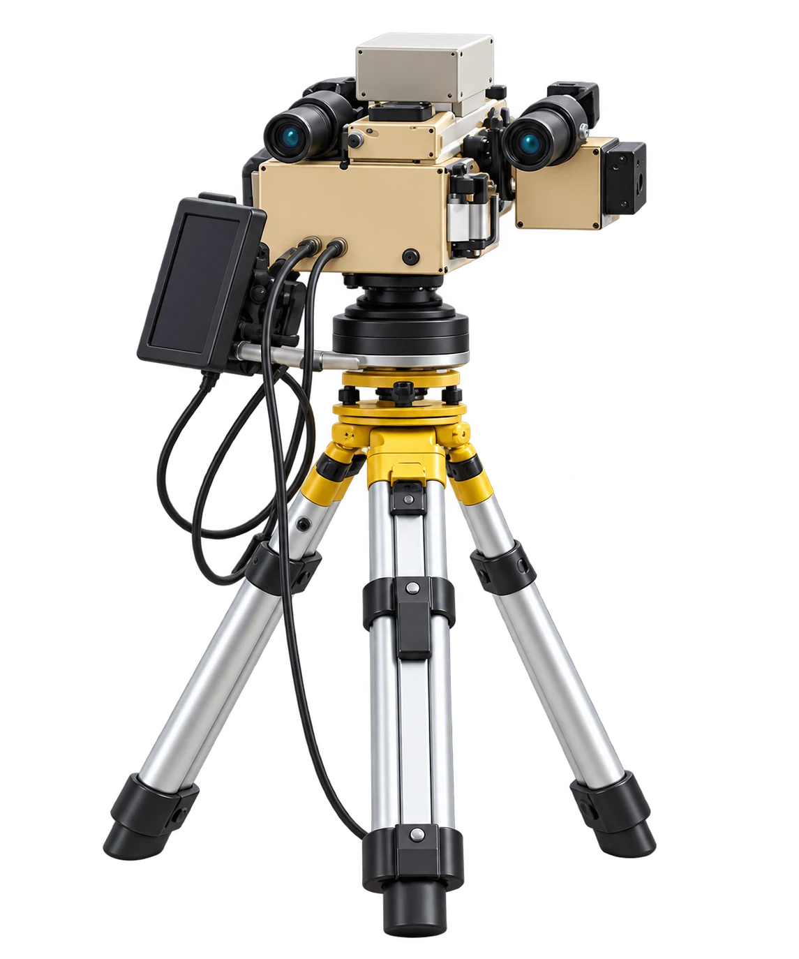
Use operating data to identify turbines requiring further investigation
Scan passing blades and analyze relative blade-angle deviations
Develop site-specific correction recommendations, then remeasure and assess performance
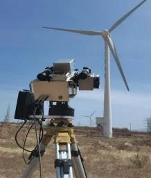
Accuracy and operating envelope require configuration-specific validation; research targets are not yield guarantees
Identify blade profiles, tower returns and outliers in the scan record
Use measurement geometry and blade profiles to calculate relative angle deviations
Combine remeasurement with operating data; energy-yield effects require comparable conditions
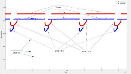
Figure illustrates the workflow; it does not establish accuracy, turbine condition or energy gain
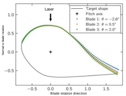
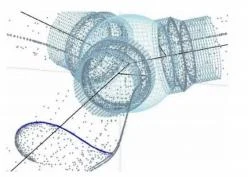
Source method illustrations, not field results; they explain the analysis approach and do not establish accuracy or energy gains.
Case and application
6.72°
Records: 0.37°
8.87°
Records: 0.18°
4.47°
Records: 0.49°
| Rank / group | Relative deviation before | Relative deviation after |
|---|---|---|
| A | 6.72 | 0.37 |
| B | 8.87 | 0.18 |
| C | 4.47 | 0.49 |
Three labeled examples; deviation is the range across three blade angles. Period, uncertainty and raw records are unavailable; no energy-gain claim.
Three labeled examples; deviation is the range across three blade angles. Period, uncertainty and raw records are unavailable; no energy-gain claim.
Case and application
Measure relative blade angles across a turbine cohort at an established wind farm.
Deploy specialist personnel for batch testing and turbine-level measurement records.
Identify relative blade-angle deviations to inform calibration and comparable retesting
Retest the same turbines under comparable conditions to assess changes in relative blade angles
Analyze abnormal path responses to help locate suspected defects
Combine continuity checks, structural information and repeat measurements
Anomaly indications require verification; a single reflection does not establish damage
Case and application
Use reflected signals to identify a suspected down-conductor anomaly for field verification.
Test conductor-end location and compare it with known structural information.
Use reflections to narrow the inspection area and check against structural and repeat-test evidence
Two source test examples; suspected damage lacks physical confirmation and does not establish accuracy
Plan measurement lines for cracks and internal-defect indications in precast concrete tower segments, informed by visual inspection.
Calibrate wave velocity in a reference area; compare measured reflections with structural thickness
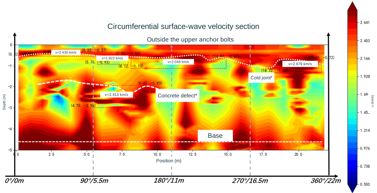
Document suspected zones, measurement records and verification recommendations for construction quality control
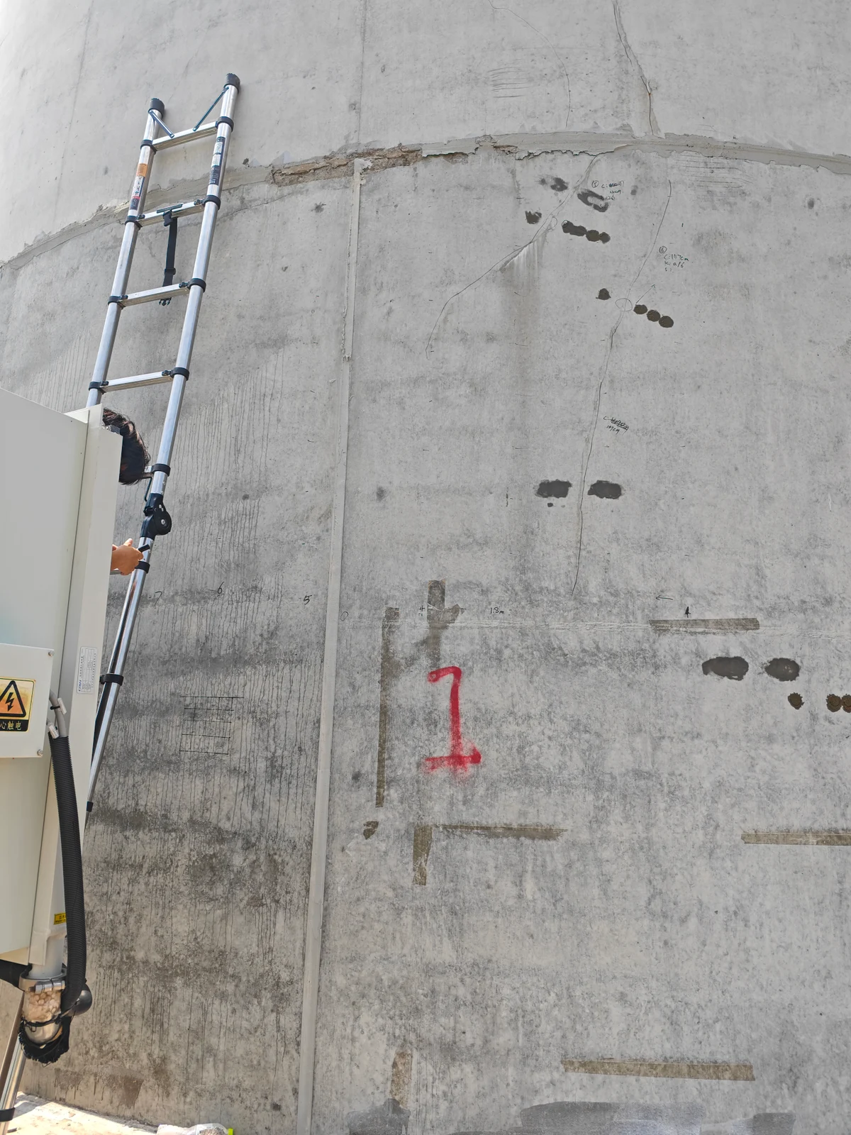
Applicability depends on structure, material, layout and calibration; assess anomalies with design, construction records and follow-up tests.
Use elastic- and surface-wave methods to identify velocity anomalies for targeted verification
Use camera calibration and 3D reconstruction to track measured points
Configure measurement for blades, towers and connections
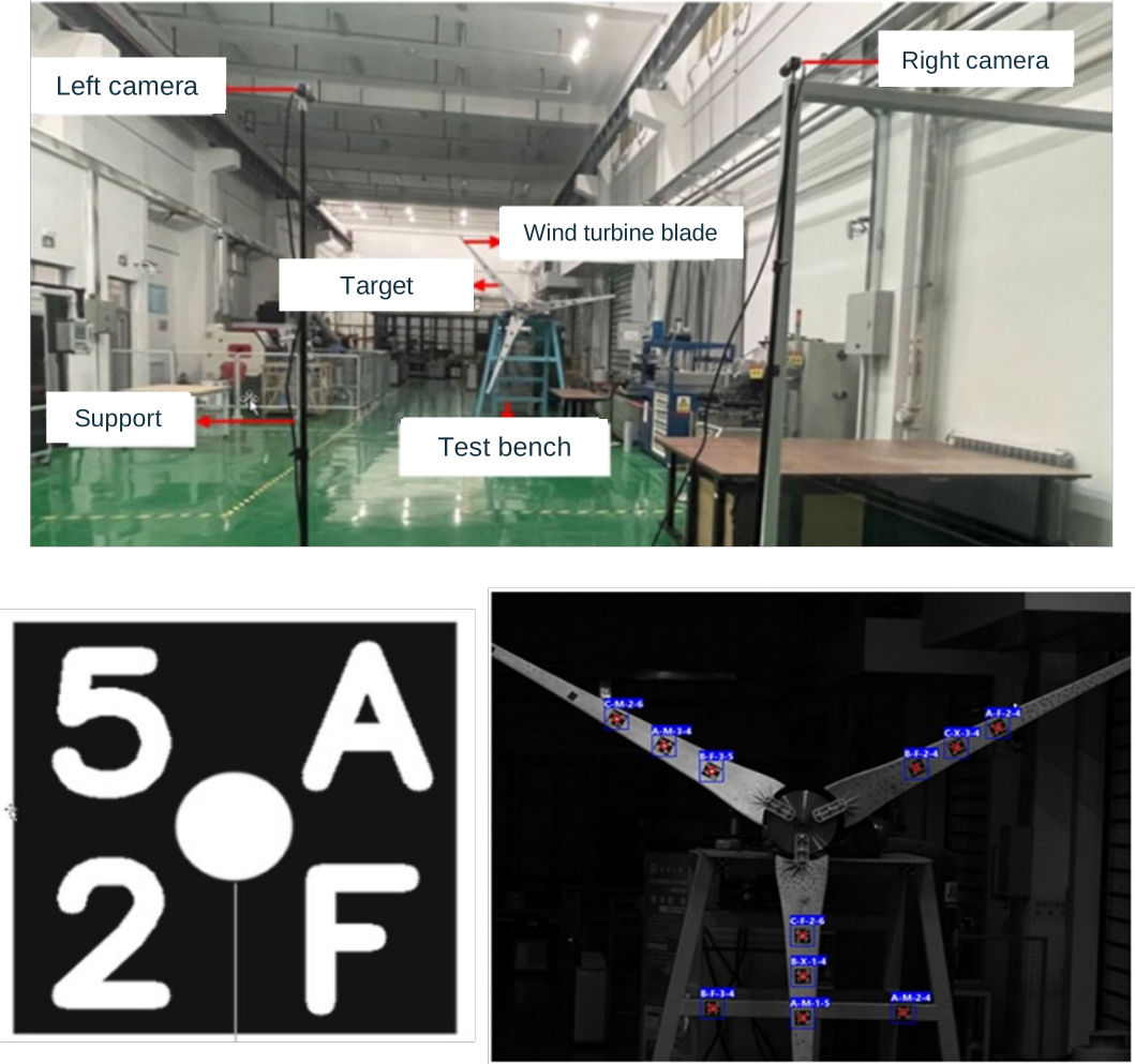
Development and test example; validate coverage and uncertainty for visibility, occlusion and conditions
Research blade and root-fastener damage detection using acoustic emission, vibration and operating data
Research links between construction defects and in-service structural condition
Use specimen, bench and field testing to establish applicability
Research directions, not claims of completed products or validated warning performance
CONTACT
Talk to us about O&M, repairs, digital solutions and inspection equipment.
Business enquiries
zhuo.wu@ds-techcn.com+86 152 3118 3837Beijing headquarters